Working with variants (D5 2.5.1.0319)

I get my models from various sources (primarily archicad and sketchup )and people, so we use skp-files for model import.

Q1 materials: i have imported model 1 and changed materials in D5 (the red ceiling in this example). after a while i get another model and import it as model 2. is there a possibility that all materials applied to model 1 are automatically applied to model 2 (having the same material name of course) or must that be done manually for every material?


Q2 model position: i imported model 1 (the poles on the 4 corner are for position reference)

then i get another variant of this model (with different object dimensions), so i used “reload from local”

but after reload the model moves, because the center of the whole skp-model stays at the same place. it would be better when the origin of the skp-file coordinate system would be used as center point when reloading, independent of the dimension.

1 Like

Yeah, you have to do it manually.

Regarding the position problem, You can “synchronise the coordinate system” of a model as soon as you import it, and then update the model later. In this way, the model will remain in place even if the overall boundingbox of the model has changed.

If the D5 converter is used in the synchronisation workflow, no misalignment problems will occur.

Causes of the problem: The coordinate system of the model imported into D5 is defaulted to point A at the bottom centre of the model, if the overall boundingbox of the model is changed before and after replacement, the position of the coordinate axes will be changed after recalculation (point B), and misalignment will occur.

After selecting the model and “synchronising the coordinate system”, the model will be restored to the absolute modelling coordinates.

For example, you have three models, a square, a circle and a rectangle, and the origin of the models is at point A (D5’s axis defaults to the bottom centre of the model). When a rectangle is deleted, the coordinate origin of the model is changed to point B.

If you align the axes, you can see that the model has moved relative to each other, i.e. the coordinates have not changed but the position of the model has changed.

hmm, not so good news. as i mentioned earlier i get the models mostly from other people (also from other companies) working with different versions of archicad (23-26). so i have to coordinate them installing and using the converter?

Yeah, you have to do it manually.

quite a task with an architectural model with a huge amount of different materials (applied in D5) used.
is a function like “copy materials (with identical name) from selected object” possible in future?

You can “synchronise the coordinate system” of a model as soon as you import it, and then update the model later. In this way, the model will remain in place even if the overall boundingbox of the model has changed.

you mean that i have to overwrite the “original_model.skp” file over and over again for every variant and do only a “reload” then there will be no movement?

If the D5 converter is used in the synchronisation workflow, no misalignment problems will occur.

getting the models from other people they have to save .d5a-files for me, right?
using “reload from local” on .d5a-files does not have this movement problem?

OMG, that’s a completely math’s nightmare.

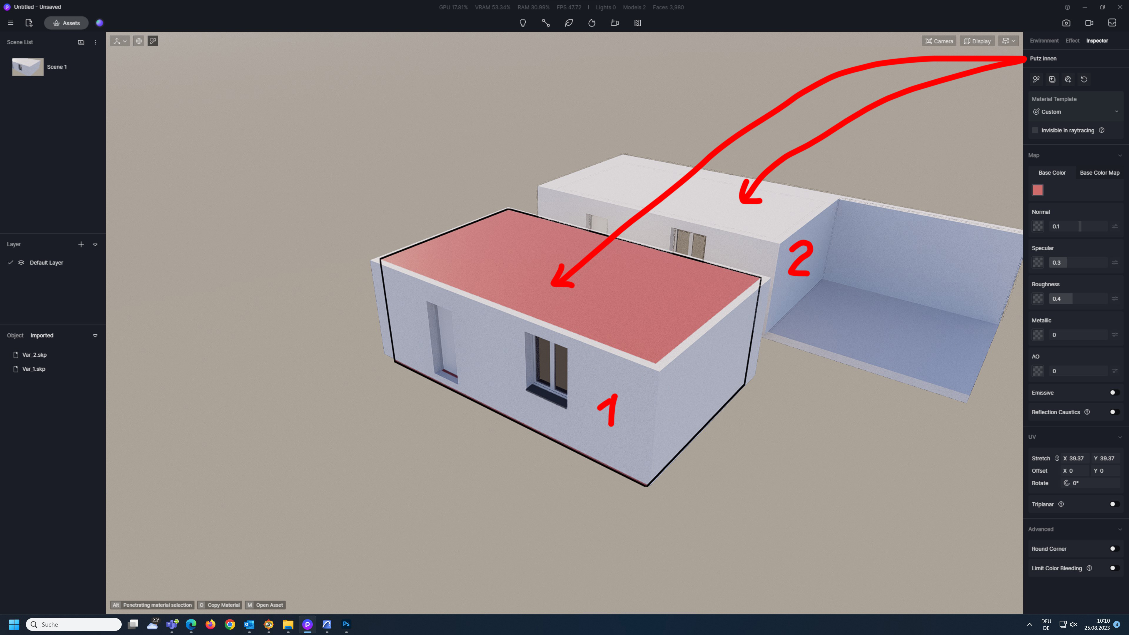
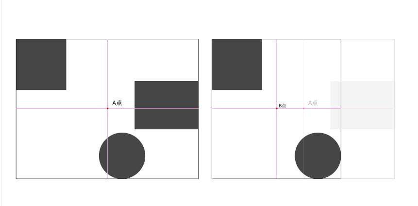
I expected that the co-ordinate system of the 0,0,0 location would determine the location of the D5 model as well. And it shouldn’t shift in relevance to the removing or adding of more or less objects inside the model and the IMPORTED MODEL FROM SOFTWARE (sketchup, archicad, blender, MAX) 0,0,0 would determine exactly where its placed within D5. The SUmodel (0,0,0) can be placed within D5 at X120,Y80,Z45 but the (SUMODEL’s 0,0,0) during import should not change itself if objects are deleted or added within the SUMODEL.
D5 shouldn’t just change the location of the 0,0,0 of the imported model-I from pointA -(to) B if the rectangle is removed. It is critical that we maintain the 0,0,0 for model-I.

For-example, if I remove the rectangle copy it with the same 0,0,0 of LocationA and make a separate file say “MODEL-II” pasteinplace the rectangle from MODEL-I and put it in MODEL-II. So it would make it so much easier for us to import “MODEL-II” and merge MODEL-I & MODEL-II with relevant center of both co-ordinates to be as 0,0,0 but they are 2 separate files people are working on. Irrelavant to where its been placed in D5 co-ordinate system.

But according to your explanation D5 automatically changes the relevant co-ordinates as per A to B if the block is removed or the sketchup file has been changed in anyway. Thats just so much of a problem to then merge new files.

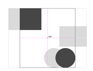
All other software’s use the above methods (Lumion,enscape,vray). including importing in between themselves FBX to SU/blender-DAE-SU, the 0,0,0 of each model is sacrosanct and shouldn’t be changed else it would be a nightmare to exactly align both XY&Z co-ordinates. we will have to manually do the match subtracting the width of the block + overlap of the block of the circle and determine the center and then calculate the new position then understand how to use that new position for any other new model.

If this was anything close to understandable lol.

1 Like

Regarding the material
Due to your importing multiple models, they come with their own MATID, hence u will have to manually give the material once each time in D5. Especially during import.

Once the same material is applied everywhere then D5 makes it even and if u change the material of the roof any one place it changes it everywhere automatically. But at initial import u will need to give the info to each model imported that the material of roof 1 and 2 are the same.

But according to your explanation D5 automatically changes the relevant co-ordinates as per A to B if the block is removed or the sketchup file has been changed in anyway.

as a workaround i used a “reference-object” (cube or cone) in a hidden place on the original model, so i can move the updated model back to it’s original place.

we will have to manually do the match subtracting the width of the block + overlap of the block of the circle and determine the center and then calculate the new position then understand how to use that new position for any other new model.

which is a nightmare, especially when getting models from other people

Due to your importing multiple models, they come with their own MATID, hence u will have to manually give the material once each time in D5. Especially during import.

i understand. but working with architectural models with dozens of materials, this is very inconvenient. so my earlier suggested “copy materials (with identical name) from selected object”-function would be very useful.

1 Like

“i understand. but working with architectural models with dozens of materials, this is very inconvenient. so my earlier suggested “copy materials (with identical name) from selected object”-function would be very useful.”

– Im guess u will need to do that within ur editing software su/max/archicad/etc and then bring it to D5 because MAT-ID has been the way for a decade now in live rendering software’s. Yes if they can implement for us to make our own material in D5 in the future and give our own MAT-ID for any surface also would be helpful as well. Currently we can duplicate materials and past to other in D5 easily. But i know where ur coming from and Yes it is a task to sit and manually give all the materials to all the imported data. But its a much rewarding aspect of live rendering :slight_smile:

Anyways Best of Luck to you.

thank you for your assistance! :slightly_smiling_face:

1 Like

please consider implementing such a “copy materials (with identical name) from selected object”-function!

Dear @Bruce.W
I would please want the devs to implement the co-ordinate system in reference to the 0,0,0 of the 3dmodelling software instead of making the implementation and moving around the 0,0,0 of the imported file as per the number of assets with in the D5file on importation.

The math’s can be extremely dis-orienting to get the final true location especially in the z axis. if not aligned properly the car movement gets a jerk down or up according to the Z axis between the 2 models.

Thanks

1 Like